
 5 Star Store
 Community Guidelines
 Newbies Corner
 Recipes
 AD search
I have a sparky who can do the work for me but he needs to know what I want him to do, since he has no idea what this is or what its trying to do.
Initially I'll plug 2 x 15A 220V 3600W (7.2kW total) elements to drive this.
I still need to buy a suitably sized control box and I'll need plugs/adapters for the control box to suit the items below.
Open to suggestions for the best/convenient plug/connection types.
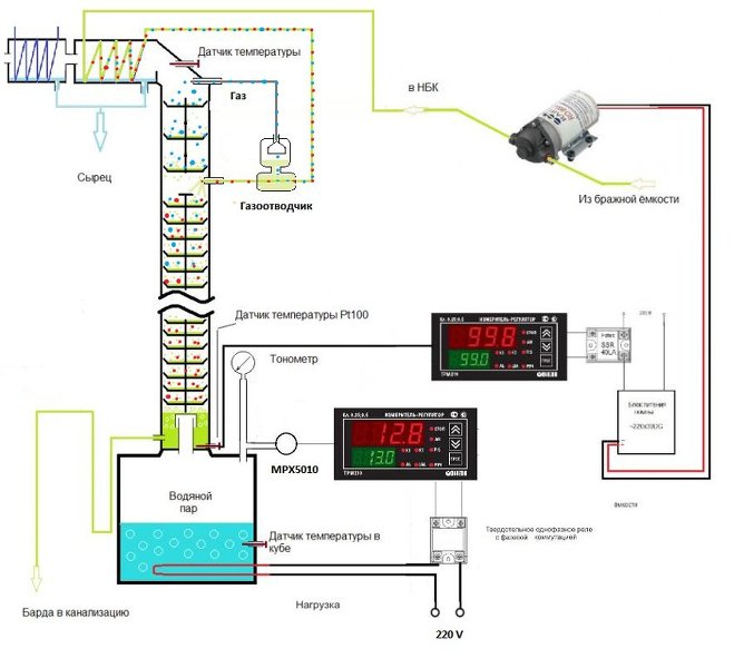
I dropped the pressure control loop and replaced it with a temperature control loop.
Parts list:
1. Digital PID Temperature Controller D1S-CR-220 4-20mA+Relay 100-240VAC
2. Digital PID Temperature Controller D1S-2R-220 relay output + relay alarm output
3. Digital PID Temperature Controller D1S-VR-220 SSR output + relay alarm output
4. RTD PT100 Temperature Sensors 1/2” NPT Threads with Detachable Connector
5. RTD PT100 Temperature Sensors 1/2” NPT Threads with Detachable Connector
6. RTD PT100 Temperature Sensors 1/2” NPT Threads with Detachable Connector
7. SSR-40LA 4-20mA to AC28-280V 40A Single Phase SSR Solid State Relay w Cover
8. 125mmx70mmx50mm Single-phase Solid State Relay SSR Heat Sink Dissipation
9. Single Phase Solid State Relay SSR-40AA 40A 150-350VAC 24-480VAC w Heat Sink
10. 110-220V To DC 12V 24V LED Strip Light Switch Power Supply Driver Transformer
11. 110-220V To DC 12V 24V LED Strip Light Switch Power Supply Driver Transformer
12. DC 12V 30W 0142 Motor High Pressure Diaphragm Water Self Priming Pump 3L/Min
Cheers,
Mech.